
 English
 Español
 Portugues
 Pусский
 Français
 Deutsch
 日本語
日本語 한국어
한국어 العربية
 Italiano
 Nederlands
 Svenska
 Polski
 ไทย
ไทย Türk dili
 Indonesia
 čeština
 Română
 Suomalainen

When I look at a terminal connector machine, I do not see the cam as just another metal part. I see it as one of the components that helps control the timing and movement of the whole mechanism. A small change in a cam profile can affect how a connected part moves, when it moves, and how smoothly the machine completes its working cycle.
That is why we developed our Custom Cam for Terminal Connector Equipment service around the actual requirements of automated machinery. At Dongguan Jifan Precision Machinery Co., Ltd., we manufacture custom cams, Cam Mechanisms, plate cams, conjugate cams, eccentric shafts, crankshafts, and other precision mechanical components. We also provide cam design, precision machining, irregular cam grinding, and Profile Grinding based on customer drawings, samples, specifications, and equipment requirements.
In practical terms, our job is quite simple: understand what the machine needs the cam to do, manufacture the component according to the agreed technical requirements, inspect the finished part, and make sure the customer receives a component that can be used as intended.
This page explains how we approach custom Terminal Connector Machine Cams, how a cam works in automated connector equipment, what we consider during manufacturing, and what information I recommend providing before requesting a quotation.
1. What Is a Custom Cam for Terminal Connector Equipment?
A cam is a mechanical component that converts rotary motion into a controlled movement. The idea is simple. A rotating cam has a specially shaped profile. A follower or another connected mechanism stays in contact with that profile. As the cam rotates, the follower moves according to the shape of the cam.
In terminal connector equipment, this type of controlled movement can be used in different stages of an automated process. The exact function depends on the machine design. A cam may control feeding, positioning, pressing, cutting, forming, insertion, transfer, or another repeated mechanical action.
Because every machine is designed differently, I do not treat a custom cam as a standard spare part. The outside shape may look familiar, but the important information is often hidden in the profile, mounting location, shaft interface, hole position, working angle, and motion requirements.
For example, two cams can have a similar diameter and thickness but produce completely different movements. One may have a short rise and long dwell period, while another may require a different motion curve. If the wrong profile is used, the cam may physically fit the machine but still fail to produce the intended movement.
That is the main reason we focus on Custom Cam Machining for terminal connector equipment rather than simply offering a generic replacement component.
Typical information I review before production
Machine model and equipment application
Original cam drawing or CAD file
Original physical sample, if available
Cam profile and motion requirements
Overall dimensions
Shaft hole or mounting interface
Keyway, bolt hole, or locating features
Material specification
Required dimensional and geometrical tolerances
Surface finish or heat-treatment requirements, where applicable
Order quantity
Inspection requirements
If the customer does not have every item above, that does not automatically mean the project cannot move forward. In replacement projects, I often start with the original component, photographs, available measurements, and basic machine information, then identify which details still need to be confirmed.
2. How Does a Cam Work in Terminal Connector Equipment?
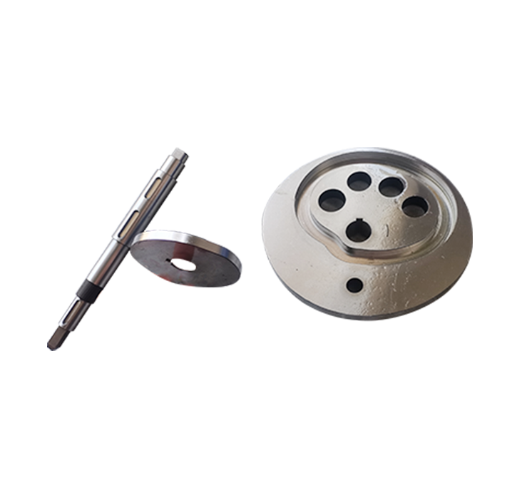
The working principle of a cam mechanism is easier to understand than it may sound.
Imagine a wheel that is not perfectly round. One section is higher, another section is lower, and the shape changes gradually around the outside. When the wheel turns, a follower touching the surface has to move to follow those changes.
That controlled movement is what makes a cam useful in automation.
For terminal connector machinery, the cam can be connected to a follower, lever, slide, shaft, or other mechanical element. The rotating movement of the cam is converted into the required movement of that component.
Depending on the equipment design, the cam profile may contain several functional sections.
| Cam Motion Section | Basic Function | Possible Effect on Machine Movement |
|---|---|---|
| Rise | Moves the follower toward a working position | Starts or increases the required mechanical movement |
| Dwell | Holds the follower near a defined position | Provides time for another machine action |
| Return | Moves the follower back | Returns the mechanism to its next cycle position |
| Transition | Connects different movement sections | Helps control changes in movement |
Source: General mechanical cam-motion principles. Product-specific motion values are not standardized and must be confirmed from the customer's machine design, drawing, or approved cam profile.
The important thing here is timing. Automated terminal connector equipment usually performs repeated movements. The machine may need one mechanism to move, stop, release, and return before another mechanism begins its next action.
The cam helps create that sequence mechanically.
When I review a custom cam drawing, I therefore do not look only at its outside diameter. I want to understand the working relationship between the cam and the connected parts.
This is especially important for precision Terminal Connector Equipment Cams. If the profile, mounting position, or reference dimensions are not correct, the machine may experience movement errors even when the component appears to be properly installed.
3. What Makes Our Custom Terminal Connector Machine Cam Different?
For us, customization does not simply mean changing the diameter of a standard cam. It means manufacturing the component around the actual equipment requirement.
Custom Cam Profile
The profile is one of the most important parts of a cam. We can process custom profiles based on customer drawings, technical specifications, or confirmed samples. Depending on the geometry and accuracy requirements, machining and profile grinding processes may be used.
For an irregular cam profile, the working surface may contain curves and transitions that require more careful processing than a simple circular component. The manufacturing method is therefore selected according to the actual geometry.
Custom Mounting Structure
Terminal connector machines can use different shaft arrangements and mounting structures. A custom cam may require a specific center hole, keyway, bolt pattern, locating feature, or other interface.
We manufacture these features according to the agreed drawing instead of assuming that one mounting design will fit every machine.
Controlled Dimensions
Dimensions that affect installation and operation need to be clearly defined before production. Where tolerances are specified, we use the customer's approved drawing as the production reference.
ISO 286-1 provides an internationally recognized system for tolerances on linear sizes and fits, including terminology for tolerance classes and basic hole and shaft concepts. It does not mean every custom cam must use one specific ISO tolerance; the actual tolerance must come from the engineering requirement for the component. ISO 286-1:2010 remains a current published edition according to ISO's official catalog.
Geometrical Accuracy
Some cam applications require more than correct length and diameter. Position, orientation, run-out, form, and other geometrical characteristics may also matter.
ISO 1101:2017 defines the symbol language and rules used for geometrical specification and provides the foundation for geometrical tolerancing. We use the customer's specified requirements as the actual manufacturing and inspection reference. ISO 1101:2017 is listed by ISO as the current published edition.
| Requirement Area | What We Review | Why It Matters |
|---|---|---|
| Cam profile | Shape, movement sections and profile requirements | Controls the intended follower movement |
| Mounting interface | Center hole, keyway, holes and locating features | Determines installation compatibility |
| Linear dimensions | Diameter, thickness, hole size and other specified dimensions | Supports proper assembly and fit |
| Geometrical characteristics | Run-out, position, orientation or form where specified | Helps control mechanical alignment |
| Surface condition | Specified machining or grinding requirements | Supports the intended contact condition |
Source: Manufacturing workflow of Dongguan Jifan Precision Machinery Co., Ltd.; dimensional and geometrical specification concepts referenced to ISO 286-1:2010 and ISO 1101:2017. Actual values are determined by the customer's approved technical documentation.
4. Our Manufacturing Process for Custom Cam Components
I always tell customers that precision machining is not just about putting a piece of metal into a CNC machine and pressing the start button.
The preparation before machining matters just as much.
For a Custom Cam for Terminal Connector Equipment, we normally move through several stages. The exact route changes according to the part design, material, quantity, profile, and inspection requirements.
Step 1: Drawing and Application Review
First, we review the customer's technical information. If a drawing is available, we check the main dimensions, profile, material, tolerances, mounting features, and inspection requirements.
If the customer sends a physical sample, we examine its structure and identify the dimensions that can be measured directly. For an old replacement cam, I also keep one thing in mind: the original component may already be worn.
That means not every measured dimension on an old part should automatically be treated as the original design dimension.
Step 2: Confirm the Critical Features
Not every dimension has the same importance.
For a cam, the working profile and mounting relationship can be especially important. A small difference in an external non-working surface may have little effect, while a change in a functional profile or shaft location could affect the entire mechanism.
Before machining, we therefore confirm the critical features with the customer where necessary.
Step 3: Material Preparation
Material selection depends on the machine environment and engineering requirements. Depending on the application, customers may specify a particular material grade or surface-treatment requirement.
We do not choose a material simply because it is common. The material should make sense for the working conditions, expected load, contact situation, wear requirements, and manufacturing process.
Step 4: Precision Machining
The blank is then processed to create the required basic geometry. Depending on the component, machining may involve turning, milling, drilling, boring, keyway machining, or other CNC processes.
The purpose is to establish the basic geometry and reliable reference surfaces before the more specialized profile work is completed.
Step 5: Profile Machining or Grinding
This is where the cam becomes a cam rather than simply a machined disc.
The working profile is processed according to the approved design. For certain precision applications, profile grinding can be used to achieve the required working geometry and surface condition.
Our experience with cam profile grinding and irregular cam grinding allows us to handle components where the working surface is more complicated than a simple circular shape.
Step 6: Dimensional Inspection
After machining, the finished component is inspected against the agreed specification. Depending on the drawing, this can include basic dimensions, mounting features, position requirements, profile-related characteristics, and surface requirements.
ISO 286-1 is useful as a reference framework for linear size tolerances, while ISO 1101 provides the language and rules for geometrical tolerancing. Again, these standards provide engineering frameworks; they do not replace the customer's specific drawing.
Step 7: Final Verification and Packaging
Before delivery, we carry out final quality checking and verification according to the agreed requirements. The component is then protected with suitable packaging for transportation.
Standard protective packaging is used for normal orders, while customized packaging can be arranged when the customer has special requirements.
| Production Stage | Main Focus | Typical Output |
|---|---|---|
| Technical review | Drawing, sample and application | Confirmed manufacturing requirements |
| Material preparation | Material and blank condition | Suitable machining starting point |
| CNC machining | Basic geometry and mounting features | Machined cam body |
| Profile processing | Working cam geometry | Finished functional profile |
| Inspection | Dimensions and specified characteristics | Verified component |
| Final verification | Overall specification compliance | Ready-for-delivery component |
Source: Dongguan Jifan Precision Machinery Co., Ltd. stated production workflow for custom precision components. The exact process route varies according to part complexity, material, quantity, profile and customer requirements.
5. Where Are These Custom Cams Used?
The keyword Custom Cam for Terminal Connector Equipment describes a specific application, but the underlying cam technology is much broader.
Terminal and connector production equipment often forms part of an automated production line. The machinery may need to perform repeated movements with consistent timing. Mechanical cams are useful in this type of system because they can create a defined movement sequence through their profile.
Depending on the machine design, custom cams can be used in equipment associated with:
Terminal connector processing
Electronic component manufacturing
Wire and cable processing
Automated assembly equipment
Connector insertion machinery
Precision feeding systems
Pressing and forming equipment
Cutting and positioning mechanisms
Special-purpose automation equipment
Custom production machinery
Our broader precision components are also used in machinery serving daily chemical products, biopharmaceutical production, food processing, electronics, plastics and hardware, printing, beverage production, and other industrial applications.
One reason I like working with different industries is that every machine teaches us something different. A cam for one piece of equipment may look similar to another, but the working requirements can be completely different.
That is why our approach starts with the mechanism rather than the product name alone.
6. How We Approach Quality and Engineering Requirements
When a customer orders a custom mechanical part, there are usually two separate questions.
The first is: Can you make the part?
The second is more important: Can you make the part according to the actual engineering requirement?
For us, the second question is the one that matters.
We Work From Confirmed Technical Information
We use the customer's drawings, specifications, samples, and equipment requirements as the foundation for production. This reduces the risk of making assumptions about a component that has a very specific function.
We Focus on Functional Dimensions
A custom cam contains many dimensions, but not every dimension has the same effect on machine operation. We pay attention to the features that affect mounting, alignment, profile movement, and interaction with related parts.
We Use Inspection as Part of the Process
Inspection should not be treated as something that happens only at the very end. Machining quality depends on correct setup, reference points, process control, and final verification.
For dimensions and geometrical requirements, the applicable customer specification remains the main reference. ISO 286-1 provides a standardized tolerance system for certain linear dimensions, while ISO 1101 provides a standardized way to communicate geometrical tolerances.
We Keep the Application in Mind
A cam is not an isolated object. It works with a follower, shaft, bearing, lever, slide, or another mechanism.
When reviewing a project, I therefore prefer to know what the cam is connected to and what movement it needs to create. Even a short explanation from the customer can sometimes answer questions that a drawing alone does not make obvious.
We Take Machinery Context Seriously
A replacement mechanical component should be evaluated within the machine and its intended operating conditions. ISO 12100:2010 provides general principles and a methodology for machinery safety, including risk assessment and risk reduction. It is a machine-level framework, not a certification claim for an individual cam. ISO 12100:2010 remains published and current while a new edition is under development.
For that reason, we do not describe a custom cam as automatically making an entire machine compliant with a safety standard. The complete machine, installation, guarding, controls, operating conditions, and risk assessment all matter.
7. Why Choose Dongguan Jifan for Custom Cam Machining?
There are many companies that can machine a round metal component. Our focus is more specific.
Dongguan Jifan Precision Machinery Co., Ltd. specializes in cam mechanisms, custom cam machining, cam design, profile grinding, eccentric shafts, crankshafts, plate cams, and conjugate cams. This means our daily work is closely connected with the kinds of mechanical components used in automated machinery.
Precision Cam Manufacturing Experience
We have experience manufacturing different cam structures and custom mechanical components. This gives us a practical understanding of the relationship between drawings, machining, profile geometry, and final inspection.
Custom Manufacturing Rather Than One-Size-Fits-All
We do not expect every customer to use the same dimensions. A terminal connector machine may have its own mounting arrangement and movement requirements. We manufacture according to the agreed specifications.
Support From Drawing or Sample
Some customers have detailed CAD drawings. Others are replacing an old mechanical component and only have the original part. We can work with the information available and identify what needs to be confirmed before production.
Broader Precision Component Capability
Our product range includes custom cams, plate cams, conjugate cams, eccentric shafts, crankshafts, and other Custom Precision Parts. If a project requires several related components, we can review the requirements as a complete mechanical project.
Inspection Before Delivery
Before delivery, products undergo machining, dimensional inspection, quality checking, and final verification according to the agreed specifications.
Flexible Logistics
Depending on destination and order size, we can arrange express, air freight, sea freight, or another suitable transportation method. Protective packaging is used during handling and transportation, and special packaging requirements can be discussed before shipment.
Our customers come to us for different reasons, but the basic requirement is usually the same: they need a precision component that matches their machine instead of a generic part that only looks similar.
8. Frequently Asked Questions About Custom Terminal Connector Equipment Cams
What is a Custom Cam for Terminal Connector Equipment?
It is a precision cam manufactured for a terminal or connector processing machine according to specific mechanical requirements. The cam converts rotary motion into a controlled movement through its specially designed profile. Its dimensions, profile, mounting structure, and material are determined by the equipment design.
Can you manufacture a terminal connector machine cam from a drawing?
Yes. A customer drawing is one of the most useful references for custom cam production. We can review the drawing for dimensions, profile, material, tolerances, mounting features, and inspection requirements before confirming the manufacturing process.
Can you make the cam from an old sample?
Yes. An original physical sample can be useful when the original drawing is unavailable. However, if the sample has been used for a long time, some surfaces may already have wear. We therefore recommend providing any available machine information or original documentation together with the sample.
Can you design the cam?
We provide cam design support based on the customer's equipment requirements. For a new design, useful information includes the required movement, machine cycle, follower arrangement, installation space, shaft speed where relevant, load conditions, and other mechanical requirements.
Do you provide profile grinding?
Yes. Profile grinding is one of our manufacturing capabilities. Whether grinding is appropriate depends on the cam geometry, material, required accuracy, surface requirements, production quantity, and other project conditions.
What materials can you use?
We can manufacture according to customer-specified material requirements. If the material has not yet been finalized, we can discuss the application conditions with the customer. The final choice should consider load, speed, contact condition, wear, machining requirements, and any applicable heat-treatment or surface-treatment requirements.
Can you manufacture small quantities?
Production arrangements depend on product complexity, material, quantity, profile requirements, and customization level. We recommend sending the drawing or sample first so we can evaluate the project and provide a suitable production plan.
What information should I send for a quotation?
I recommend sending the following information whenever possible:
Product name or machine application
2D drawing or 3D CAD file
Original cam sample, if available
Material requirement
Quantity
Dimensional tolerances
Cam profile information
Surface treatment or heat-treatment requirement
Photos of the installed component, if useful
Delivery destination
If some of these details are unavailable, send what you have. A photograph and a basic description of the machine can still be a useful starting point.
How long does production take?
There is no single production time for every custom cam. The production cycle depends on complexity, material, quantity, profile, machining requirements, inspection requirements, and customization level. We confirm the expected production schedule after reviewing the project details.
How do you package the finished cams?
We use standard protective packaging to help prevent damage during handling and transportation. For special requirements, customized packaging can be arranged according to the customer's needs.
How are payment terms arranged?
Payment terms are arranged according to the contract and may depend on order quantity, production requirements, and project conditions. The exact payment arrangement is confirmed before the order is placed.
Conclusion: A Practical Custom Cam Solution for Connector Machinery
A cam may be a relatively small component compared with an entire terminal connector production line, but its role in mechanical motion can be important.
When the cam profile, mounting dimensions, position, and related features are properly matched to the equipment, the component can perform its intended function within the machine's motion system. When those details are ignored, even a visually similar replacement part can create fitting or operating problems.
That is why we take a practical approach to every Custom Cam for Terminal Connector Equipment project.
We start with the customer's drawing, sample, or equipment requirements. We review the functional features. We select the appropriate machining route. We use CNC machining, profile processing, and grinding where required. We inspect the finished component against the agreed specifications and package it appropriately for delivery.
At Dongguan Jifan Precision Machinery Co., Ltd., our capabilities cover more than one type of cam. We manufacture custom cams, cam mechanisms, plate cams, conjugate cams, eccentric shafts, crankshafts, and other precision mechanical components for automated machinery and production equipment.
If you are looking for a custom terminal connector machine cam, precision cam for connector equipment, terminal connector equipment replacement cam, or a custom-machined cam based on an existing sample, you can send us the drawing, CAD file, sample information, or machine requirements.
I would rather review the actual engineering details before making a promise about the part. Once the requirements are clear, we can discuss the suitable manufacturing process, inspection requirements, production cycle, packaging, and delivery arrangement.
That is the approach we believe works best for precision mechanical components: understand the machine first, manufacture the part carefully, check what was made, and deliver according to the agreed requirements.
Technical References
The following official ISO references are used in this article to explain general dimensional and geometrical specification concepts. They are not presented as product-specific certifications or as proof that every customer cam must use the same tolerance values.
ISO 286-1:2010 — Geometrical product specifications (GPS) — ISO code system for tolerances on linear sizes — Part 1: Basis of tolerances, deviations and fits. ISO states that this standard establishes the ISO code system for tolerances used for specified linear sizes and defines related concepts and terminology. Official ISO reference.
ISO 1101:2017 — Geometrical product specifications (GPS) — Geometrical tolerancing — Tolerances of form, orientation, location and run-out. ISO states that this standard defines the symbol language and rules for geometrical specification. Official ISO reference.
ISO 12100:2010 — Safety of machinery — General principles for design — Risk assessment and risk reduction. ISO describes this standard as providing general terminology, principles, and a methodology for machinery safety risk assessment and risk reduction. Official ISO reference.
Technical note: Dimensions, tolerances, materials, cam profiles, surface treatments, and other product-specific specifications should always be confirmed from the customer's approved drawing, sample, or technical documentation. The comparison tables in this article describe our manufacturing approach and general engineering principles; they are not undisclosed specifications of a particular terminal connector machine.
