
 English
 Español
 Portugues
 Pусский
 Français
 Deutsch
 日本語
日本語 한국어
한국어 العربية
 Italiano
 Nederlands
 Svenska
 Polski
 ไทย
ไทย Türk dili
 Indonesia
 čeština
 Română
 Suomalainen

When I look at a liquid chromatography instrument, I do not only think about pumps, columns, detectors, and software. A modern LC system also contains many small mechanical parts that make the instrument move, switch, position, inject, or control a process. Some of these components may never be noticed by the end user, but they can still be important to the machine's mechanical operation.
Our Custom Camshaft for Liquid Chromatography Instruments is made for this type of application. We manufacture custom camshafts according to customer drawings, equipment structures, motion requirements, dimensions, materials, and tolerances. Depending on the instrument design, a camshaft can be used to control or transmit repeated mechanical movement inside an autosampler, valve mechanism, sample handling system, pump-related mechanism, positioning assembly, or other automated laboratory equipment.
At Dongguan Jifan Precision Machinery Co., Ltd., we specialize in Custom Cam Machining, Cam Mechanisms, cam design, Profile Grinding, eccentric shafts, crankshafts, plate cams, conjugate cams, and other precision mechanical components. Our focus is not on producing one standard camshaft for every machine. We build the component around the actual equipment requirements.
In this product guide, I will explain what a custom camshaft does, where it may be used in liquid chromatography equipment, which dimensions matter during manufacturing, how we machine and inspect the part, and what information you should provide when requesting a quotation.
1. What Is a Custom Camshaft for Liquid Chromatography Instruments?
A camshaft is a rotating mechanical component that carries one or more cams. The cam profile controls the movement of a follower, lever, roller, slider, or another connected mechanism. As the shaft rotates, the follower follows the cam surface and moves according to the shape of the profile.
That sounds complicated, but the basic idea is actually quite simple. Think about a wheel with a specially shaped edge. If a small roller touches that edge while the wheel turns, the roller will rise and fall according to the shape of the wheel. A camshaft uses this basic principle in a more precise and controlled form.
In laboratory automation, this type of mechanical movement can be useful when a machine needs to repeat a particular sequence. Instead of using a separate motor for every small movement, a cam mechanism can coordinate several mechanical actions from one rotating drive.
A liquid chromatography system normally contains several major modules. Agilent describes a typical LC system as having a pump, sampler, column, and detector, with each module performing a specific role in the separation and detection process.
A camshaft is not normally considered one of the four main analytical modules. It is better understood as an internal mechanical component that may be used inside an automated module or supporting mechanism. This distinction is important because I do not want to suggest that every HPLC or UHPLC instrument uses a camshaft.
Why Would an LC Instrument Need a Camshaft?
Automated chromatography equipment contains many movements. A sample vial may need to be positioned. A needle may need to move to a specific location. A valve may need to rotate or switch. A mechanism may need to press, release, lift, or return to its starting position.
Modern autosamplers, for example, can contain sample compartments, injection units, sample loops, injection valves, selector valves, metering devices, and other mechanical assemblies. Thermo Fisher's documentation for a UHPLC autosampler shows these types of internal components.
Some equipment uses motors and electronic controls for these movements. Other designs may use mechanical linkages, cams, gears, eccentric components, or combinations of these systems.
If the machine uses a cam-driven mechanism, the camshaft becomes a very important mechanical interface between the drive system and the moving components.
Custom Is Important
A standard camshaft is not always suitable for laboratory equipment. The shaft may need a specific length, diameter, cam profile, phase angle, bearing seat, keyway, mounting structure, or surface finish.
This is why we manufacture a custom camshaft for chromatography equipment according to the actual technical requirements. The goal is not simply to make a shaft that looks similar. The goal is to make a component that matches the mechanical relationship specified by the equipment designer.
2. How Does a Camshaft Work in Liquid Chromatography Equipment?
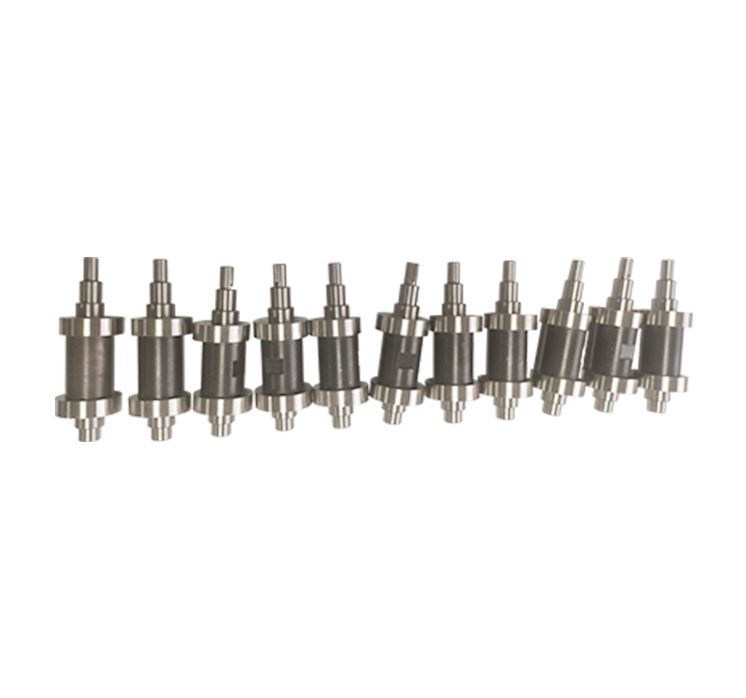
The working principle of a camshaft is based on controlled mechanical motion. A motor or another drive source rotates the shaft. As the cam rotates, its profile pushes against a follower or roller. The follower then moves according to the profile.
If the profile rises gradually, the follower can move gradually. If the profile stays at the same height for part of the rotation, the follower can remain in a fixed position for that section. When the profile falls, the follower returns.
These basic movements can be arranged into a sequence of rise, dwell, return, or other motion patterns. The exact motion depends on the cam profile.
A Simple Example
Imagine an automated sample-handling mechanism that needs to move a component forward, stop for a short period, and then return. A properly designed cam can create this sequence through one continuous rotation.
The shaft provides the rotation. The cam profile provides the movement. The follower transfers that movement to the working component.
In a real chromatography instrument, the mechanism may be much smaller and more complicated, but the basic principle remains the same.
Cam Profile Controls Movement
The most important part of a cam is not always the shaft diameter. It is often the cam profile. The profile determines how the follower moves as the shaft rotates.
This is why our work involves both Custom Camshaft Machining and cam design. When the customer already has a completed drawing, we manufacture according to that drawing. When a customer is developing a new mechanical system, we can discuss the required cam geometry and manufacturing approach.
Phase Angle Also Matters
If a camshaft contains more than one cam, the angular relationship between the cams can be critical. For example, one cam may need to start moving a mechanism while another cam is holding a different mechanism in position.
This is known as the phase relationship. A small angular error can change the timing of the connected mechanism.
For this reason, when I manufacture a Precision Camshaft for liquid chromatography instruments, I pay attention not only to individual dimensions but also to the relationship between working features.
Camshaft Compared With Eccentric Shaft
| Feature | Camshaft | Eccentric Shaft |
|---|---|---|
| Basic Principle | Cam profile controls follower movement | Offset center creates eccentric movement |
| Motion Control | Can create rise, dwell and return profiles | Often creates a simpler repeated movement |
| Main Design Feature | Cam profile and phase relationship | Eccentric distance and shaft geometry |
| Typical Connection | Roller, follower, lever or slider | Connecting rod, bearing or linkage |
| Best Fit | Controlled and sequenced mechanical movement | Offset rotary-to-reciprocating movement |
Source: This table summarizes general mechanical principles used in automated machinery. The actual mechanism selected for a liquid chromatography instrument depends on the equipment designer's motion requirements.
I do not automatically recommend a camshaft simply because a customer asks for one. If an eccentric shaft, crankshaft, linear actuator, or another mechanism is more suitable for the required movement, that should be considered during the machine design stage.
3. Where Can a Custom Camshaft Be Used in Liquid Chromatography Instruments?
Liquid chromatography is a broad field. HPLC and UHPLC systems contain pumps, samplers, columns, detectors, valves, tubing, control electronics, and other modules. Agilent and Thermo Fisher both show modular LC architectures containing these major components.
A custom camshaft may therefore be used in a supporting mechanical mechanism rather than directly inside the analytical flow path.
Autosampler Mechanisms
Autosamplers automatically move samples and perform injection operations. Agilent's current multisampler products, for example, use automated sample management and robotic movement to handle vials and microplates.
A camshaft may be relevant to a particular mechanical subsystem where controlled repeated movement is required. Depending on the equipment architecture, this could include a positioning mechanism, lifting mechanism, lever system, or another automated movement.
Sample Injection Mechanisms
Sample injection is a key part of LC analysis. The sample must enter the mobile phase and then travel through the column. Thermo Fisher describes the normal LC flow sequence as mobile phase delivery, sample injection, separation on the column, and detection.
In an automated instrument, mechanical parts may be used to position injection components or operate supporting mechanisms. A custom camshaft can be designed for these movements when the equipment structure calls for it.
Valve and Switching Mechanisms
LC systems often use valves to control flow paths. Some systems also include switching valves and other flow-control components. Thermo Fisher's LC documentation, for example, identifies injection valves, solvent valves, selector valves, and check valves within an autosampler assembly.
If a valve or switching mechanism requires mechanically controlled rotation or linear movement, a cam-driven mechanism may be considered by the equipment designer.
Metering and Positioning Mechanisms
Accurate sample handling can require controlled movement. Current LC autosamplers can use metering devices and automated sample handling systems.
Where a machine requires a fixed mechanical sequence, a cam mechanism can provide repeatable movement without relying entirely on electronic motion control.
Laboratory Automation Equipment
The same camshaft manufacturing technology can also be used for other analytical instruments and laboratory automation equipment. These may include sample preparation machines, automated testing equipment, dispensing systems, inspection machines, and other precision equipment.
Typical Application Areas
| Equipment Area | Possible Mechanical Function | Why Custom Geometry May Be Needed |
|---|---|---|
| LC Autosampler | Positioning, lifting or linkage movement | Compact internal structure |
| Injection System | Mechanical actuation or positioning | Specific timing and travel |
| Valve Mechanism | Switching or controlled movement | Specific rotation or phase relationship |
| Sample Handling | Pick, move, return or positioning action | Custom machine layout |
| Laboratory Automation | Repeated mechanical sequences | Equipment-specific motion profile |
Source: Application examples are based on documented LC system architectures and autosampler components from Agilent and Thermo Fisher Scientific. The use of a camshaft in any specific instrument depends on its internal mechanical design.
4. Main Features of Our Custom Camshaft
When I manufacture a camshaft for an analytical instrument, I pay close attention to the details that affect installation, movement, and repeatability. A small component may contain several different machining requirements.
Custom Cam Profile
The cam profile is manufactured according to the customer's drawing or agreed design. Depending on the application, the profile may include different rise, dwell, and return sections.
If the customer provides an existing cam profile, our job is to reproduce the specified geometry accurately. If the design is still being developed, the required movement needs to be confirmed before production.
Customized Shaft Dimensions
Shaft diameter, overall length, shoulders, grooves, keyways, threaded sections, mounting areas, and other features can be customized according to the equipment design.
Multiple Cam Configurations
Some camshafts contain more than one cam. In that case, the position and phase angle between the cams can be important. We manufacture the shaft according to the specified arrangement.
Precision Bearing Seats
Bearing locations need to match the equipment assembly. A correct bearing fit helps keep the shaft in its intended position during operation.
The actual fit should always follow the engineering drawing and bearing manufacturer's requirements. I do not recommend using a generic fit simply because it worked on another machine.
Stable Mechanical Movement
A properly machined camshaft helps the follower remain in the intended relationship with the cam profile. This is important when the mechanism performs repeated cycles.
Custom Surface Requirements
Depending on the design, certain surfaces may require grinding or specific surface finishing. We provide profile grinding and irregular cam grinding services for precision motion components.
Dimensional Inspection
Before delivery, products undergo dimensional inspection, quality checking, and final verification according to the agreed specifications.
Suitable for Small Precision Components
Laboratory instruments often have compact internal structures. A custom camshaft can be manufactured around the available installation space instead of forcing the equipment designer to use a standard component with unsuitable dimensions.
5. Technical Considerations When Designing a Precision Camshaft
From my experience with custom mechanical parts, the biggest problems usually do not come from the obvious dimensions. They often come from the relationship between several dimensions.
Cam Profile Accuracy
The profile determines how the follower moves. If the profile is different from the intended design, the movement can change.
This is why profile grinding and careful inspection can be important for certain camshaft applications.
Pressure Angle
The pressure angle describes the relationship between the follower movement and the force direction generated by the cam. A poor cam design can increase side forces and mechanical stress.
For a replacement component, we normally follow the existing design rather than changing the pressure angle without engineering approval.
Follower Type
The cam profile needs to match the follower. A roller follower, flat follower, or other follower design can have different contact requirements.
When quoting a custom camshaft, information about the follower can therefore be useful, especially for a new design.
Phase Relationship
If multiple cams are installed on one shaft, their angular relationship should be controlled according to the machine sequence.
A camshaft is often not just a collection of individual cams. It is one coordinated mechanical component.
Shaft Alignment
The main shaft needs to maintain the required relationship with its bearings and connected components. Misalignment can increase wear and affect the movement of the follower.
Surface and Wear Considerations
The cam surface may experience repeated contact with a roller or follower. Material selection, hardness, surface condition, lubrication, and operating conditions can all influence service life.
Dimensional Relationships
A camshaft can include many important dimensions:
Main shaft diameter
Cam outside diameter
Cam width
Base circle dimensions
Lift or working height
Cam profile
Angular position
Bearing seat dimensions
Keyway or mounting dimensions
Overall shaft length
Surface finish requirements
Material and heat treatment requirements
Not every project needs all of these dimensions to be specified in the same way. The customer's drawing and equipment design determine which characteristics are critical.
Camshaft vs. Standard Shaft
| Requirement | Standard Shaft | Custom Camshaft |
|---|---|---|
| Specific Cam Profile | Usually unavailable | Designed or machined to requirement |
| Multiple Cams | Limited options | Custom positions and phase angles |
| Special Shaft Length | Depends on catalog | Manufactured to drawing |
| Special Bearing Seats | Limited standard sizes | Customized dimensions |
| Integration With Existing Equipment | May require modification | Designed around existing requirements |
Source: This is a practical manufacturing comparison based on the nature of custom camshaft machining. Standard components may be suitable for some machines, while custom components are useful when the equipment requires non-standard geometry.
6. How We Manufacture a Custom Camshaft for Liquid Chromatography Instruments
I always prefer to start with the drawing rather than immediately discussing the machining process. The drawing tells us what the component needs to be. The application information tells us why those dimensions matter.
Step 1: Technical Drawing Review
We review the customer's 2D drawing, 3D model, sample, or technical specification. Important information includes material, dimensions, tolerances, cam profile, shaft length, bearing seats, mounting features, surface requirements, and quantity.
Step 2: Application Review
If available, I also like to understand where the camshaft will be installed. For example, is it part of an autosampler, valve mechanism, sample handling unit, or another automated module?
This information does not replace the drawing, but it can help us understand which characteristics may be important during manufacturing and inspection.
Step 3: Material Confirmation
The material is selected according to the customer's specification and application requirements. Factors may include strength, wear resistance, machinability, hardness, surface treatment, and operating conditions.
For laboratory equipment, the customer's engineering team should confirm the final material requirement where the component is part of a validated instrument design.
Step 4: CNC Turning
CNC turning can establish the main shaft geometry, including diameters, shoulders, grooves, and other rotational surfaces.
Step 5: Cam Machining
The cam working geometry is machined according to the specified profile. Depending on the design, different machining and finishing processes may be used.
Step 6: Profile Grinding
When the design requires precision profile finishing, grinding may be used to achieve the specified geometry and surface condition.
Our experience in custom cam machining and profile grinding allows us to support different cam configurations rather than limiting the production to simple standard profiles.
Step 7: Secondary Machining
Keyways, holes, threads, slots, flats, grooves, and other features can be processed according to the drawing.
Step 8: Dimensional Inspection
The finished component is inspected according to the agreed specifications. Critical characteristics may include shaft diameters, cam dimensions, profile-related features, angular positions, bearing seats, and mounting dimensions.
Step 9: Final Quality Verification
Before delivery, we complete final quality checking and verification. The goal is to make sure the finished part is consistent with the agreed technical requirements.
Step 10: Protective Packaging and Shipment
We use protective packaging to reduce the risk of damage during transportation. Depending on the destination and order size, products can be shipped by express, air freight, sea freight, or another suitable method.
Customized packaging can also be arranged for customers with special requirements.
| Stage | Main Work | Key Information |
|---|---|---|
| Technical Review | Review drawings and specifications | Dimensions, profile, tolerances |
| Material Confirmation | Confirm material requirements | Material grade and treatment |
| CNC Machining | Machine shaft geometry | Diameter, length, shoulders |
| Cam Machining | Create cam working geometry | Profile and phase position |
| Grinding | Finish precision surfaces | Profile and surface requirements |
| Inspection | Check critical dimensions | Agreed inspection criteria |
| Final Verification | Confirm overall compliance | Customer specification |
| Packaging | Protect finished component | Shipping method and special requirements |
Source: The production and inspection workflow reflects Dongguan Jifan Precision Machinery Co., Ltd.'s stated custom machining, cam design, profile grinding, dimensional inspection, quality checking, final verification, and protective packaging capabilities.
7. Why Choose Dongguan Jifan for Custom Camshaft Machining?
For a custom camshaft, I believe the supplier needs to understand more than basic CNC machining. The supplier should understand how the part moves and how the part fits into the machine.
We Specialize in Cam Mechanisms
Cam mechanisms are one of our core areas. We manufacture custom cams, cam mechanisms, plate cams, conjugate cams, eccentric shafts, crankshafts, and other precision motion components.
This experience is useful when working with customers who need a camshaft for automated equipment rather than a simple round shaft.
We Support Custom Cam Design
We can work from customer drawings and specifications. For projects where the cam design is still being developed, we can also discuss the required motion, mechanical structure, and manufacturing considerations.
The final design should always be confirmed by the customer's engineering team, especially when the camshaft is part of a laboratory instrument or regulated analytical system.
We Work With Precision Grinding
Our capabilities include profile grinding and irregular cam grinding. These processes can be useful when the cam profile requires controlled finishing beyond basic machining.
We Manufacture According to Customer Requirements
We do not force customers to choose from a fixed list of shaft dimensions. We can manufacture according to drawings, specifications, samples, and equipment requirements.
We Understand Different Industries
Our precision components are used in automated machinery across industries including electronics, biopharmaceutical, daily chemical, food processing, plastics and hardware, printing, beverage, and other production equipment.
Liquid chromatography instruments are another specialized application where compact precision components may be required.
Inspection Before Delivery
Every custom component needs to be checked against the agreed requirements. Before delivery, we perform machining, dimensional inspection, quality checking, and final verification.
More Than 1,000 Customers
Our products have been trusted by more than 1,000 customers. We continue to focus on reliable quality and professional service rather than making unrealistic performance claims.
Flexible Production and Logistics
Production time depends on product complexity, material, quantity, and customization requirements. Payment terms are arranged according to the contract and project conditions.
For transportation, we can arrange express, air freight, sea freight, or another suitable method according to the destination and order size.
8. FAQ About Custom Camshaft for Liquid Chromatography Instruments
Q1: What is a custom camshaft for liquid chromatography instruments?
It is a specially manufactured camshaft designed for a specific liquid chromatography instrument or supporting automated mechanism. The camshaft can control or transmit repeated mechanical movement according to its cam profile.
Q2: Is a camshaft a standard component in every HPLC instrument?
No. HPLC and UHPLC systems have common modules such as pumps, samplers, columns, and detectors, but their internal mechanical designs can vary. A camshaft is an application-specific mechanical component when the equipment uses a cam-driven mechanism.
Q3: Where can a camshaft be used in an LC instrument?
Depending on the equipment design, it may be used in an autosampler mechanism, sample handling system, positioning assembly, valve mechanism, injection-related mechanism, or another automated mechanical subsystem.
Q4: Can you manufacture the camshaft according to our drawing?
Yes. We manufacture custom camshafts based on customer drawings, 3D models, samples, specifications, and equipment requirements.
Q5: What information should I provide for a quotation?
Ideally, please provide a 2D drawing or 3D model, material, quantity, overall shaft dimensions, cam profile, cam width, phase angle, bearing dimensions, tolerances, surface requirements, and any heat treatment or finishing requirements.
Q6: Can you manufacture a replacement camshaft?
Yes. If you have an original drawing or physical sample, we can review it for replacement production. Additional information about the equipment and assembly can be useful when the original drawing is unavailable.
Q7: Can you make multiple cams on one shaft?
Yes, depending on the design. Multiple cam profiles can be machined on one shaft, with their positions and phase relationships produced according to the engineering drawing.
Q8: Do you provide profile grinding?
Yes. We provide profile grinding and irregular cam grinding services for precision motion components. The actual finishing process depends on the profile, material, tolerance, and surface requirements.
Q9: Can you help with cam design?
We provide cam design and Custom Cam Machining Services. If the mechanism is still under development, we can review the available technical information and discuss the manufacturing side of the cam design.
Q10: What materials can be used for a custom camshaft?
Material selection depends on the equipment design and engineering requirements. We manufacture according to the specified material grade and agreed production conditions.
Q11: How do you inspect the camshaft?
We inspect the finished component according to the agreed technical requirements. Depending on the project, inspection can cover shaft dimensions, cam dimensions, profile-related characteristics, phase positions, bearing seats, and other critical features.
Q12: How long is the production cycle?
Production time depends on the complexity of the camshaft, material, quantity, machining process, and customization requirements. We confirm the expected production schedule after reviewing the technical information.
Q13: Can you manufacture other LC instrument components?
Our main focus is precision mechanical components such as custom cams, cam mechanisms, plate cams, conjugate cams, eccentric shafts, crankshafts, and related custom parts. We can discuss other mechanical components according to your equipment requirements.
Q14: How do you package precision camshafts?
Standard protective packaging is used to reduce the risk of damage during transportation. Customized packaging can also be arranged for special requirements.
Q15: Can you provide small-batch custom camshafts?
Custom production can be discussed according to the component complexity, material, quantity, and project requirements. Please send the drawing and quantity so we can review the manufacturing conditions.
Q16: How do I start a custom camshaft project?
Send us your drawing, 3D model, sample information, or equipment requirements. If possible, include the cam profile, shaft dimensions, material, quantity, critical tolerances, and application information. We can then review the project and discuss the manufacturing process.
Conclusion: Building the Camshaft Around the Instrument
A camshaft may be a relatively small component, but it can have an important job inside automated equipment. Its profile controls movement, its shaft connects the mechanism, and its phase relationship can determine when different mechanical actions happen.
For liquid chromatography instruments, I believe the most practical approach is to treat the camshaft as part of the complete mechanical system. The pump, autosampler, valves, column, detector, electronics, and mechanical components all have their own roles. Modern LC systems are built from multiple coordinated modules, so a custom mechanical component needs to fit the actual instrument structure.
At Dongguan Jifan Precision Machinery Co., Ltd., we manufacture Custom Camshaft for Liquid Chromatography Instruments according to customer drawings, specifications, samples, and equipment requirements. Our capabilities include custom cam machining, cam design, profile grinding, irregular cam grinding, eccentric shaft machining, crankshaft machining, plate cams, conjugate cams, and other precision mechanical components.
If you are developing an HPLC or UHPLC instrument, an automated laboratory system, an autosampler mechanism, or another analytical machine that requires a custom camshaft, send us your technical drawing or existing component information.
I will focus on the practical details: the cam profile, shaft dimensions, material, tolerances, phase position, bearing seats, machining process, inspection requirements, quantity, and delivery conditions.
The goal is straightforward. We want to manufacture a camshaft that matches the machine it was designed for, passes the agreed dimensional checks, and is ready to become part of the customer's production or analytical equipment.
Technical References
Agilent Technologies, LC Instrumentation Fundamentals — overview of typical liquid chromatography system components and flow path. [Agilent LC Instrumentation Fundamentals](https://www.agilent.com/cs/library/primers/public/LC-Handbook-Complete-2.pdf?utm_source=chatgpt.com)
Thermo Fisher Scientific, HPLC Basics: What You Should Know — overview of HPLC pumps, autosamplers, columns, detectors, and analytical flow. [Thermo Fisher HPLC Basics](https://www.thermofisher.com/blog/analyteguru/hplc-basics-what-you-should-know/?utm_source=chatgpt.com)
Thermo Fisher Scientific, Vanquish Neo System Operating Manual — examples of autosampler internal mechanical components including injection units, valves, sample loops, and metering devices. [Thermo Fisher Autosampler Components](https://docs.thermofisher.com/r/Vanquish-Neo-System-VN-A10-VN-C10-VN-P10-VN-S10-Operating-Manual/925215499v2en-US925249931?utm_source=chatgpt.com)
Agilent Technologies, 1260 Infinity III Multisampler — example of automated sample management, vial and microplate handling, and injection mechanisms. [Agilent 1260 Infinity III Multisampler](https://www.agilent.com/en/product/liquid-chromatography/hplc-components-accessories/hplc-injectors/1260-multisampler?utm_source=chatgpt.com)
Technical note: The tables in this article are practical engineering comparisons intended to explain product selection and manufacturing concepts. They are not universal specifications for all liquid chromatography instruments. Actual camshaft dimensions, materials, tolerances, profiles, loads, speeds, and operating conditions should be confirmed from the customer's equipment design and engineering drawings.
